
This circuit is used to convert single pole 12 throw switch to into binary output.
As the maximum bit is 12 (position) which is represented as 1100 in binary hence we need 4 data lines as output
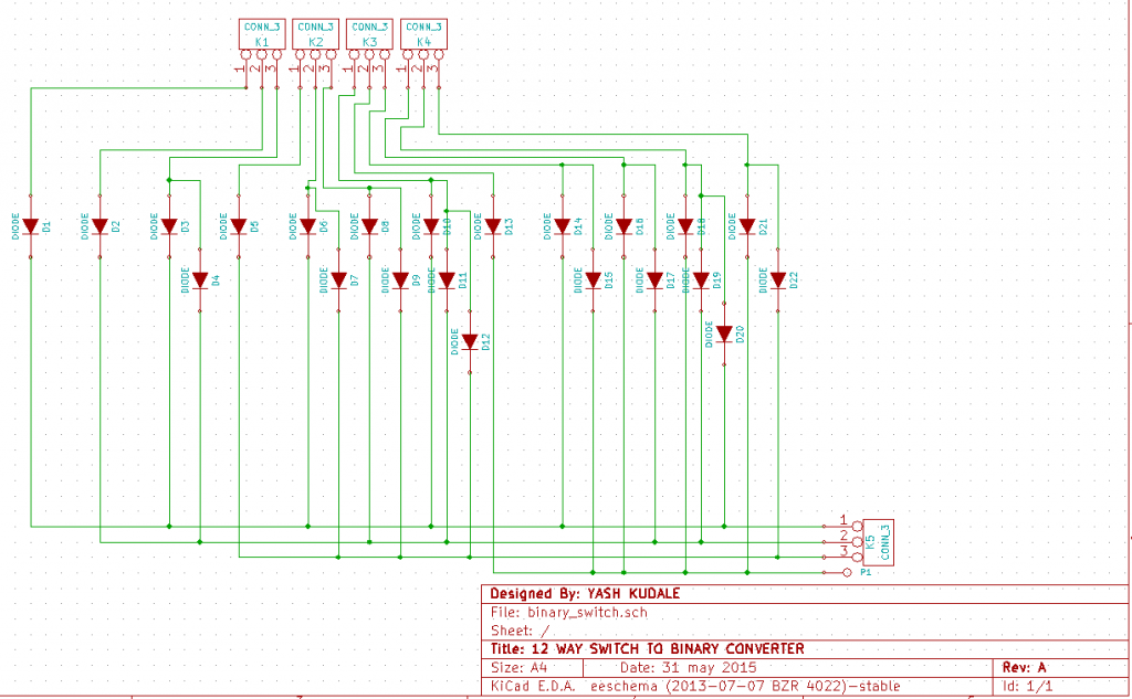
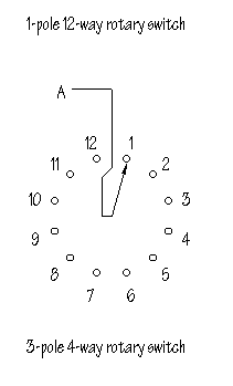
Here in the image above we can see each input position has diodes connected to it so one line doesn’t turn on the other lines, K1, K2, K3, K4 are 12 inputs, power is connected to the A point of the switch (see fig 1) as the knob is rotated from 1 to any 12 positions and the power flows through the respective power line which is connected to the data line (K5 and P1) through diodes hence converting the switch position to binary output. It’s a simple and elegant design that just works.
*Diodes are to be chosen according to voltage and current needed.
It can be used to give 12 position rotary switch input to micro-controller using only four digital pins instead of 12 which is always great!
Here is the link for the Gerber files enjoy, happy-making!


