
Over-current protection is a type of circuit protection that stops your designs from releasing the magic smoke (getting damage). In some ways, most over-current protection circuits help with the over-voltage condition too. It’s because as the voltage increases, the current draw increases too.
What are our options for over-current protection?
The simplest form of over-current protection is adding a current limiting resistor. It works on simple Ohm’s law and dissipates power as heat. As one can imagine, it’s great for driving an LED, but it is not suitable for higher current.
There are many other off-the-shelf options available that are more complicated in design and more efficient. But what I was looking for needed to be simple/cheap but didn’t affect the signal while in normal operating range.
Design Tips: Using depletion mode MOSFETs for over-current protection
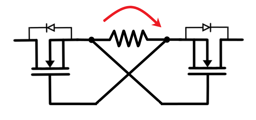
To achieve this, we are going to use a depletion-mode MOSFET with a series resistor. It’s a simple circuit.
To understand it’s working, first, let’s refresh the types of MOSFETs.
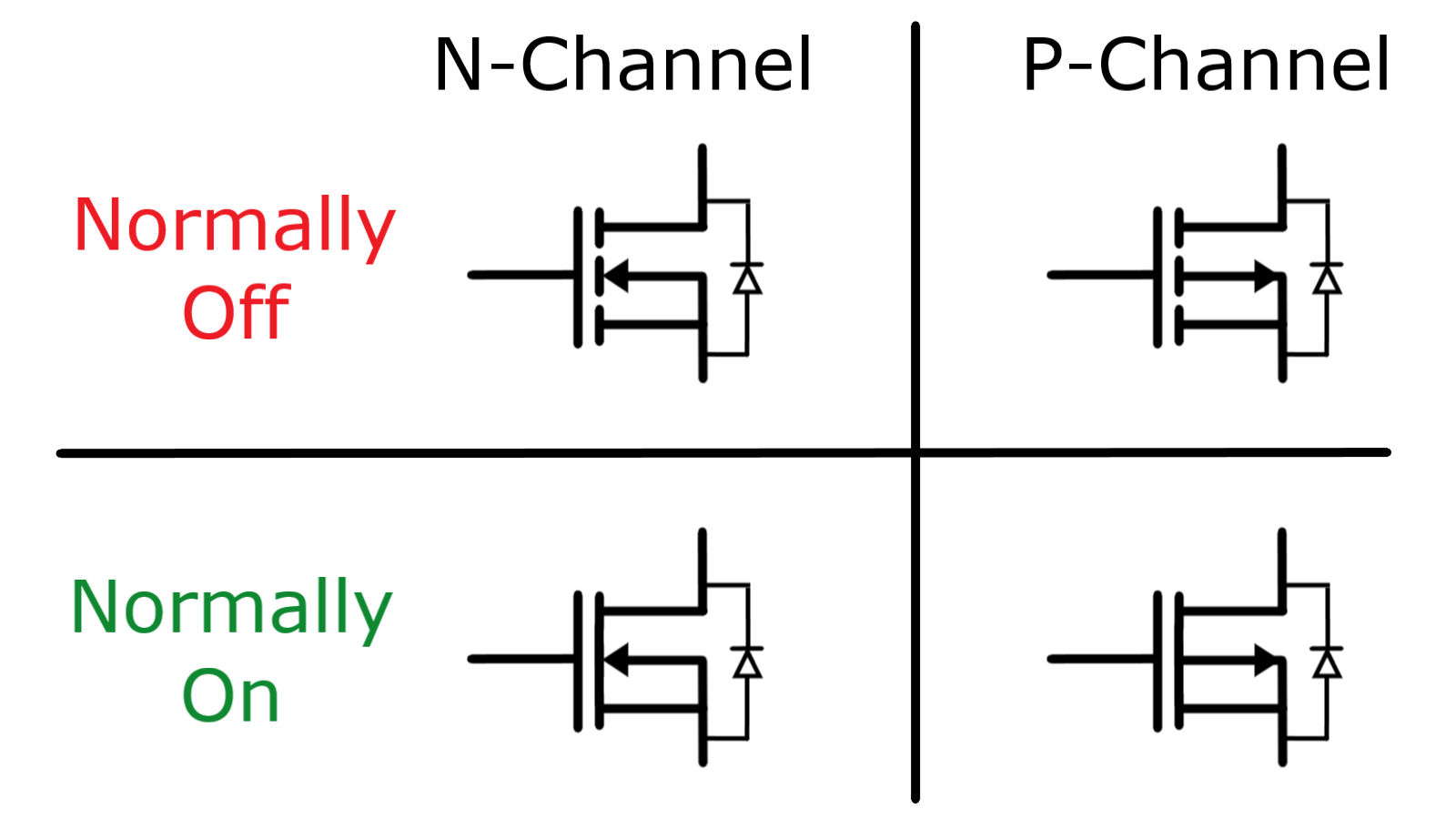
We all know the basic two types of MOSFETs, N-Channel and P-Channel. But there are also lesser-known characteristics called enhancement mode and depletion mode in MOSFET.
I try to remember them as ‘normally off’ for enhancement-mode MOSFET and ‘normally on’ for depletion-mode MOSFET.
Do note the difference in symbols for enhancement and depletion mode MOSFET. Due to the prevalence of the enhancement-mode MOSFET, people rarely follow the symbol convention.
In the circuit, the depletion-mode MOSFET act as a closed switch with a resistance equivalent to its Ron resistance.
Due to which current starts flowing through the resistor, generating a voltage drop. When the voltage goes over the MOSFET’s threshold voltage, the MOSFET stops conducting, preventing over-current situations.
The calculation for the value of resistance takes into account the threshold voltage of the MOSFET.
During general operation, resistance is low enough, keeping the MOSFET off but adequate so that MOSFET turns off as the current flowing through resistance increases.
Let’s see some graphs
Enough of this boring theory. Let’s see some graphs.
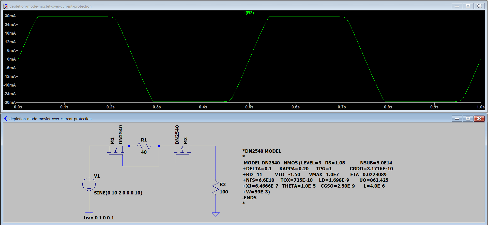
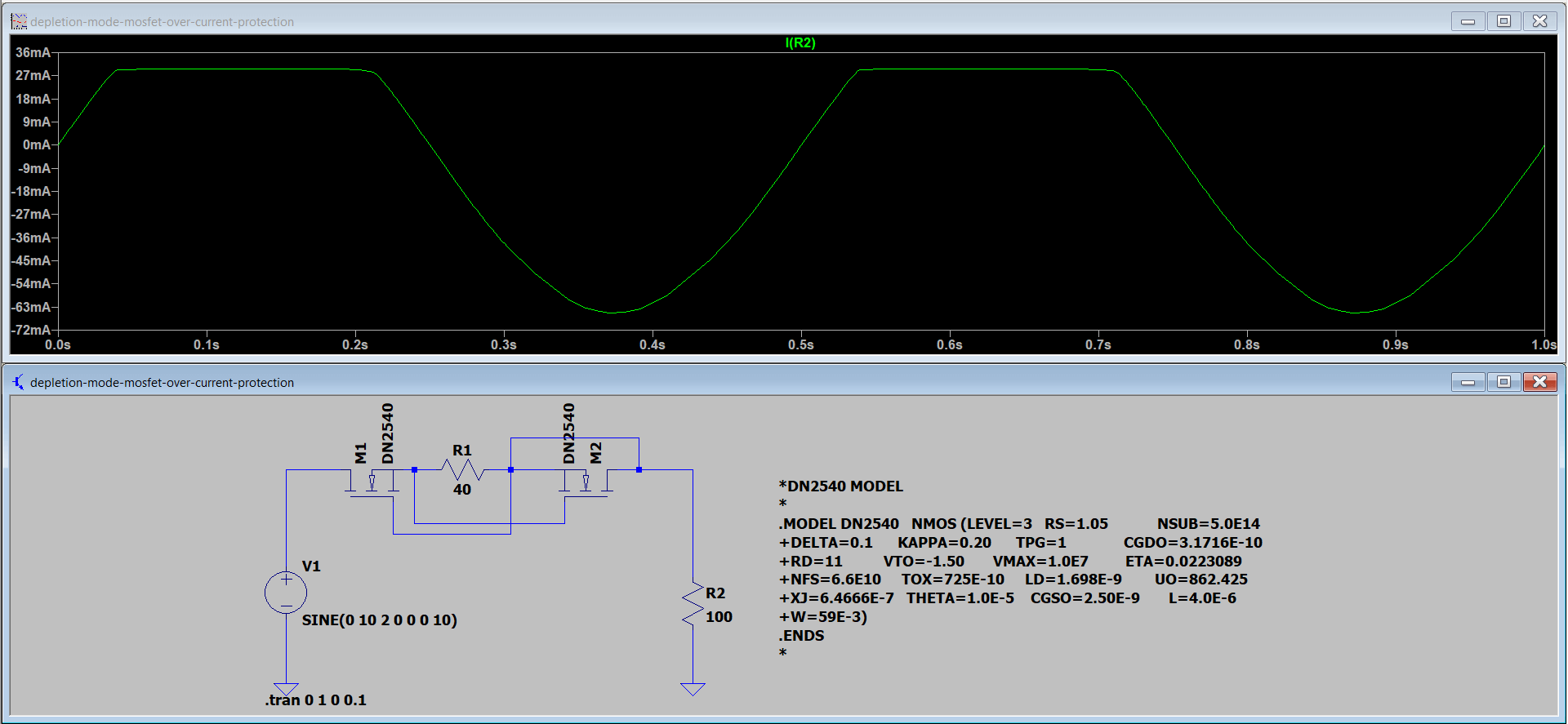
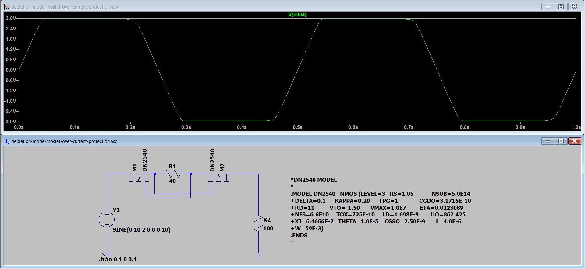
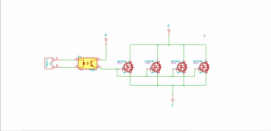
I have used DN2540 N channel depletion mode MOSFET. The configuration shown is bi-directional over current protection. But you can use just one MOSFET if you require just unidirectional protection, shown below.
As you can see, circuit design limits the load to draw anything more than 30mA in just one direction.
Finally, I have shown the same circuit working as over-voltage protection.
What’s the catch?
I found this circuit novel and simple. One of the drawbacks of the circuit is that the Ron resistance of the MOSFET with the series resistance creates a voltage drop. Especially for lower current values.
References
You can find more circuits using depletion-mode MOSFET in this Microchip’s app note.

