In need for power supply in your upcoming project?
Confused between Linear and Switch Mode Power supply?
or just want to understand how they work?
Let’s find you some answers-
This will be a three-part blog post
- Introduction
- Choosing Right Supply for your Project
- Design
PART 1: Introduction
It’s a long post so get comfy, bring your favorite beverage, take a deep breath and now lets start!
Let us try and understand what each of them really are and how do they differ.
Certainly if you are reading this you are a newbie so we will not go much in the complicated working (for now) of each and every component but we will try to just keep it simple and create just an intuitive understanding of each device.

Consider you’re getting a 12V from a battery and you need to power your Arduino which needs 9V. So you need to drop your voltage by 12v-9v= 3v you then recall the Ohms Law (V=IR) and calculate that for a 3v drop with 200mA (say) you need a 15ohm resistor in series with your battery. Well now you might say that’s it we got out 9v and everyone is happy. But wait let’s say after using your battery for few hours it’s voltage drops to 10v, but our 15ohm resistor for the same amount of current is still dropping 3v which corresponds to 10v-3v = 7v. At 7v our Arduino will not work.
To overcome this problem we need a control system which looks at the output voltage and changes its resistance accordingly. For this to work, we need to use a transistor specifically BJT – Bipolar Junction Transistor, in its active region it acts like a resistor where its resistance is proportional to the current flowing through its base terminal or we can say its a current controlled variable resistor.
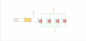
Here we measure the output voltage through the feedback resistors and feed it to an error amplifier, this error amplifier now controls the current flow through the base which changes the resistance, thus increasing or decreasing the voltage drop across the transistor.
See the below image for a basic block diagram of such a control system.

This is nothing but very simplified Linear Regulator
This transistor used in above circuit is called a series pass transistor
Ok, then we got our fix voltage output which will remain constant irrespective of fluctuation in the input voltage so we are done, right ? Well not yet.
Let us consider an example say you have the same battery of 12v but now you are got a device to power which works on 3.3v. No problem you say just add a 3.3v regulator and off you go. But wait let’s do a simple thermal calculation. We need to drop 12v-3.3v = 9v (approx) through the transistor, say now we need 1A for our new device, So now Power dissipated through this transistor can be given by Pd = V x I.
Pd = 9 x 1 = 9 watts of power. This 9W of power is dissipated as heat.
It’s a lot of heat to be dissipated through a TO-220 package in which most of the Linear regulator comes in and its just gets worse with an increase in voltage difference (between input and required voltage) and increase in current requirement.
This power dissipation mainly because we are using the transistor in its active region (which as explained earlier works as a variable resistor). We here need the transistor to act like a switch which will reduce the power loss.

So now instead of wasting power by driving BJT in the active region (of its characteristic graph) we can use it in its Saturated and Cutoff region basically as a switch.
To understand how this voltage changes, consider yourself switching your light switch on – off at very high rate where the off and on time are the same, on an average your light will get half the maximum power and thus produce half the light intensity. So simply increasing “on” time will increase the output voltage. This topic will seem familiar if you have worked with PWM signals.
Now keeping the feedback system the same as we used in a linear regulator, we will change just the error amplifier where instead of giving current change with respect to output voltage we will switch transistor “on” and “off” and change the “on” time according to the output voltage. So if the voltage is more than the set voltage the “off” time will increase and vice versa.

This system is nothing but a switching/ switched mode power supply.
Again this is a highly simplified version, we have not added any energy storage element or discussed any of its topologies but for now, this is enough to get a general idea.
Up till now we have considered BJT in our examples where we are using them just the Saturated and Cutoff mode we can replace it with a MOSFET.
Why? you ask, MOSFET has very small active region and it is mainly developed to be used as a switch, they have very low “on” resistance when they are conducting, this reduces losses further and they also have a very high switching frequency compared to BJTs.
Next time we will see what we have to keep in consideration while choosing a power supply for your next project.

Pingback: Choosing right power supply for your project | YashRK
Woah! I’m really enjoying the template/theme of this website. It’s simple, yet effective. A lot of times it’s difficult to get that “perfect balance” between superb usability and appearance. I must say you have done a excellent job with this. Additionally, the blog loads very quick for me on Chrome. Superb Blog!
I truly appreciate this post. I’ve been looking everywhere for this! Thank goodness I found it on Bing. You’ve made my day! Thx again!