
Project
We have to drive a 500W motor using a PIC16F877A, measure its RPM and also feeding it back to the microcontroller to displaying its real-time speed on a 16×2 LCD Character Display.
Solutions
There are many solutions available for motor control from more efficient motor driving IC to making your own H-bridge or using a high side or low side switching control.
We will be using a low side switching technique to control the motor as it is possible to control a high wattage motor with the least amount of parts and circuit complexity.
Design
Power Supply
You could use any power supply SMPS or Linear just it needs to deliver the same voltage which motor will be needing (for us it was 24V your will depend on the motor). We will be using a Plate type transformer which will deliver 24V at 20A (max), then we will be using a single-phase bridge rectifier KBPC3510 which has a maximum rating of 1000V at 35A (max). We will be providing four 23000uF electrolytic capacitors so that the ripple produced will be low even at higher currents. LCD & Micro-Controller will be working on 5V so we will be using an LM7805 which will deliver 5V at 1A (max).
Micro-Controller
The micro we will be using is PIC16F877A whose datasheet is linked here. I have chosen it due to its number of I/O ports and its memory.
LCD Connections
LCD used here is generic 16 x 2 character display, we can use it in 4 bit or 8 bit mode, for this project we will be using it in 4 bit mode as it saves us precious I/O pins and we don’t have much data to push to the LCD so the 8 bit mode is not needed.
Below is the image in which you can see the connections to be made with the micro, note that only four data pins are going to the micro and others are grounded, hence the 4-bit mode.
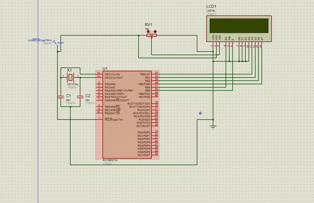
(Please do note the pin number when connecting LCD with the micro in the real world as the pin layout in the image is not exactly same as in real IC itself). Data Sheet for LCD is here though you may not need to refer it.
Mosfet Driver Circuit
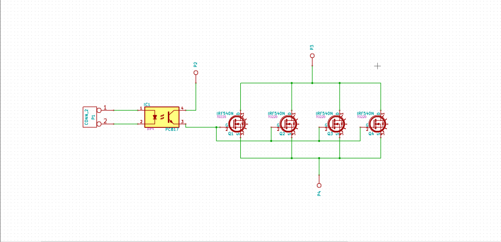
Here we are using four IRF540 in parallel configuration to increase the current capacity of the circuit, each MOSFET is rated for 100V and 28A which is around 2800W of power transfer but if we used only one MOSFET then the 500W (for what we are designing) flowing through the MOSFET will heat it up a lot (please check its datasheet for exact heat calculations). So after a few back-of-the-envelop calculations, I found four MOSFET will be good enough which actually makes it capable of transferring 11.2 kW of power. (Note that you can also use it with 2 or less MOSFET by providing proper heat sink). We have used the PC817 optocoupler to keep the high power side isolated from the micro-controller.
RMP Measurement
There are various methods of measuring RPM using driven motor configuration, IR pulse detecting, using a Hall effect sensor. Here we will be using driven motor configuration, RPM measurement is done by the secondary motor which is connected with the main motor using a belt and pulley. This motor gives 35V at maximum RPM which is then converted into 4V (using voltage divider circuit) to maintain it in 0-5V range of micro, then it is fed back to micro on analog (pin no 2) which is then converted back into RPM in micro-controller then displayed by using LCD.
Programming
Micro-controller programming is done in Mikro C, code is well commented so its easy to understand. All the code can be downloaded from the download section below.
Connections
Motor’s positive is directly connected to the 24V power supply, then “P3” of the motor driver is connected to the negative terminal of the motor and point “P4” to the negative terminal of the power supply (ground).
MicroController board is powered by LM7805 5V DC output, the pin no 17 is the PWM output which is than connection to the 220-ohm resistor in series than to a red LED than to pin 1 of PC817 on motor driver broad then its pin two is grounded.
Power supply connections will differ with the type of supply you choose. Other connections are covered in the Gerber files. All download links are given down below.
Reference and Links
Special thanks to Siddhant Sawant.
Downloads
All Gerber files, code and other related files for this project – Link
Please share this post and if you build this project, notify me and send me your modifications, I will update this blog and give you a shout out for that.
I discovered your site internet site on google and check several of your early posts. Keep in the very good operate. I merely extra your Rss to my MSN News Reader. Seeking toward reading far more from you down the road!…