
Most of us find ourselves in a situation where we need a precision current excitation source for one or the other sensors. The easiest way to have that is to use an ADC with a built-in current source.
In these ICs, an internal voltage source generates the excitation currents. ADC measurements use the same reference voltage. So the drift in the sensor and other non-idealities gets compensated out by design.
But when sensors have higher resistance, the compliance voltage needed to generate the current also goes up.
I found myself in a situation where I had to check the accuracy of a resistive sensor. The maximum current I could achieve with the ADC was 750uA. But the accuracy, drift, and the other non-idealities mentioned in the datasheet, were tested on 1mA or 1.5mA excitation current.
So I needed a precision current source with enough voltage headroom to get that 1-1.5mA of current. Instead of changing the ADC, I just decided to design a precision current source.
Working Principle:
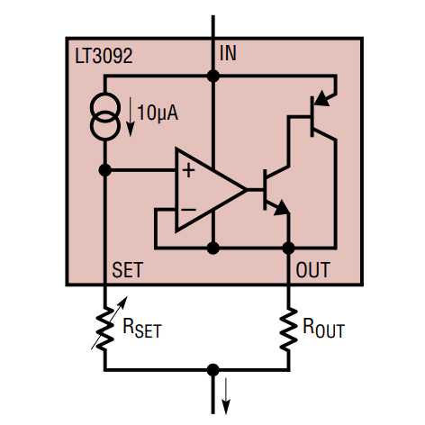
There are many ways to skin this cat. I wanted something simple and elegant. Few hours of searching on the interwebs and a few inspirational projects later, I found LT3092. It is a two-terminal programmable current source with a range of 0.5mA to 200mA. It also has a wide input voltage range hence solving our issue with the limited voltage headroom.
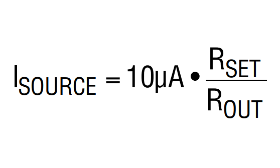
The IC has a 10uA of a current source. This current source with a Rset resistor sets the voltage at the non-inverting terminal of the opamp. And as the opamp tries to maintain an equal voltage between its two inputs drives the transistors at its output. Current flowing through the transistor causes a voltage drop across the Rout resistor. Opamp senses the voltage across the Rout resistor. As you can imagine, if the Rset > Rout, we get an amplification of current at the output, as a higher amount of current is needed flowing through the Rout resistor to achieve the same amount of voltage drop.
Design Requirements:
- Three current ranges
- 500uA
- 1000uA
- 1500uA
- < 0.1% accuracy
- Trimming circuit for calibration
- Battery-powered
- Power indicator
Design Considerations:
To achieve low-temperature drift, we will be using resistors from the same series, so as the temperature rises, they drift equally.
We need to use a boost converter to achieve high voltage headroom on a battery-powered device.
To set three ranges of current, we will need three different resistor values. To minimize the BOM items, we will try and standardize the resistors as much as possible.
Trimmer resistors will allow us to have the capability of calibrating the output current. These have notoriously high PPM/°C. So most probably, we will have a higher temperature drift.
Some back of the envelope battery life calculations:
We will need at least 2V at the output when the battery is 80%-90% depleted. Our current consumption is quite straight forward it is the current output of the device plus the current consumed by the LED. Equating it with a boost efficiency of 70%. So with three AA batteries, we can expect to get 336hrs to 1400hrs of battery life.
In the next post, we will go through the schematic of the device. We will also discuss the design decisions made in detail.

Pingback: Precision Current Source : Part Two | Yash Kudale's | Personal Blog
Pingback: Update & Upcoming Projects | Yash Kudale's | Personal Blog
Pingback: Precision Current Source : Part Three - Yash Kudale's | Personal Blog