As my family eagerly planned our holiday for the New Year, I found myself lost in a different kind of excitement. While they scoured the internet for the perfect hotel, my mind was busy cooking up a new project. I envisioned a sleek device that could measure ambient temperature and display it in real time. But let’s be honest—who wants to carry around a dull, square PCB? That’s when inspiration struck, and I set out to create ThermoTag, a stylish keychain fit for Gotham’s guardian!
Batman’s Keychain – ThermoTag
A simple device with a temperature sensor, microcontroller, and a display. Mounted on a Batarang-shaped PCB.
Isn’t it all so simple? But unfortunately, this post is about how feature creep creeps in and how things go south.
Let me show you the final device.
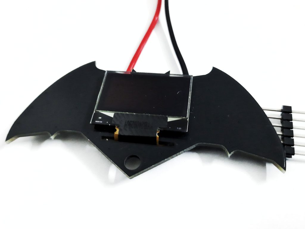
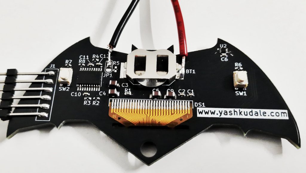
Here, you can see the beautifully cut PCB from JLC PCB. By the way, you can read about my experience with them here.
At the front, we have a 0.96-inch OLED display with its flat flex cable neatly tucked in the back. The back has two buttons, a microcontroller, a coin cell battery holder in the middle, and a tiny temperature sensor on the right side.
Design
I started by thinking about the form factor for the device.
I had a few goals to accomplish:
- The device should be something that I carry daily, like my wallet or keys.
- No boring square-shaped PCBs. I make enough of them at work.
- The device needs to be battery-powered.
Thus, I landed on the idea of a keychain in the shape of Batman’s Batarang.
After completing the relatively simple schematic, I started the PCB design. I looked at many Batman logos and selected one with a wider middle section to accommodate the display and battery. Being a keychain, it needed to be handy. To decide on the device size, I printed the logo in multiple sizes on paper. Cutting them out and playing with them gave me a maximum size for the PCB.
This is when I discovered a CR2032 would not fit on the keychain. I also wanted the Batman’s ears on the PCB to match the face drawn on the display, which constrained me with the overall size and positioning.
In the remaining area, only a CR1620 cell with its holder can be fitted. I was not afraid of the battery life as I would keep the display mostly off and turn it on only after a button was pressed.
Building the device
I didn’t want to use an OLED module on my PCB, which would have made it thicker. And where is the fun in using off-the-shelf modules? Thus, I started by referencing other OLED module designs online and creating one of my own. Most of my component selection was limited to what I could quickly procure from a local vendor, which informed my choice of microcontrollers and other passive components.
I made a few assumptions. The OLED display driver has a built-in DC-DC converter, which boosts the voltage to drive the LCD. I noted that this display is mostly powered by 3.3V, but I assumed a 3V input might still work due to the built-in converter.
I finally assembled the device. It was my first time soldering a display’s flex cable, but it wasn’t difficult at all. Due to space constraints near the display region, I chose a 0402 capacitor. Those gave me a bit of a hard time with soldering iron but reflowing them was easy.
Challenges
Once the first PCB was built it was time for programming but as soon as I started to port the U8g2 library on the controller I realized my first mistake. The library will not fit the memory available on the STM32F030. Unfortunately, there was no pin-compatible microcontroller available for me to replace it. Then I found a lighter-weight library meant only for SSD1306 display driver. Using the library I managed to fit some images and text on the screen but nothing too fancy.
But the consequence of my earlier assumptions was waiting for me. Once the library complied I tried uploading it, but for the longest time, the display would not show anything. Initially, I thought that the coin cell wasn’t able to provide a sufficient amount of current for the display to work properly. Later I found out the assumption I made about the internal DC-DC converter was wrong and it was not able to pump up the voltage high enough to drive the display.
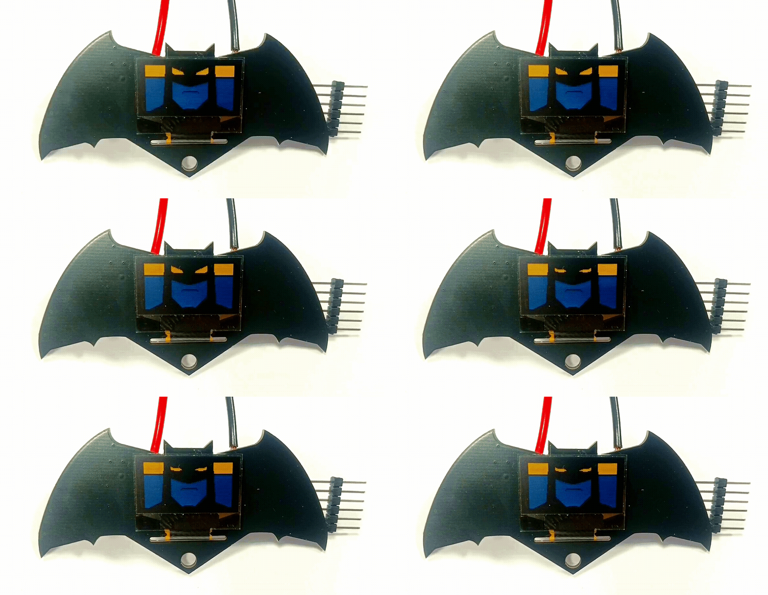
So, the device “works” when connected to an external power source at 3.6V, and can only show a couple of images. Thought, the temperature sensor worked perfectly fine.
In conclusion
While the circuit didn’t quite work as I had hoped, it still is a stunning piece of art in its own right. I shared the beautiful PCB with my friends, to use it as a unique accessory. This experience reminded me that even when things don’t go as planned, the beauty of creativity can still shine through.