
There are always these few projects which seem simple on the surface. But once you start getting into the nitty-gritty, it ends up teaching you a lot. This constant current dummy load is one of those projects.
Let us first understand the use of the project.
Say you have bought a new battery for your project. And you want to discharge it to see its performance. Or say you just built a power supply, and now you want to load the power supply. To see how it performs under various load conditions. Your primary option is to use multiple high wattage resistors in combination to get the right amount of load. You also have to keep swapping the resistances to check for various load conditions. But there is a better way. You can use an electronics load. Using it, you can set the amount of current needed, and it will load your circuit/battery for that current. Also, you can make it draw maximum current at a specific voltage or set a constant wattage, but we are sticking to the basics here.
Origin
I first saw this circuit made by Dave Jones on EEVBlog. He made the device circuit look very simple. Which it is, but there are lots of details you can get into later on, especially once you start building it with the parts you have laying around.
This blog post is not an explanatory blog for the circuit. But if you want that, Dave and many other YouTubers have done a fabulous job. I just made this circuit early on during my engineering for one of my other projects as a test instrument. Earlier this year, I installed the whole project in a case. And now I have decided to make the PCB for it to add active cooling to it. So I thought, might as well document it and share the files so others can make it for themselves. I will be mostly be using off-the-shelf parts. To make the project easily replicable. There are a few changes I have made to the original circuit. To make the device even more useful. I have explained the changes made below.
Please find the Schematic PDF file and other design files on my GitHub page.
Overview
Let start by taking an overview of the schematic and understand the component choices I made along the way.
The device is called Constant Current Dummy Load. It’s a fully analog design and with no digital logic in it. It’s intended to test a few low-power DC-DC Converters design. Hence I didn’t need a large heat sink for power dissipation. And considering its relatively low power use case. I decided to have a maximum 2A load with 1A and 2A range switch. Due to which I can get the full range of 2A. But also have a fine range selection for lower currents. I am using a 10-turn pot for setting the load current.
If you see the schematic, we have mainly three sections here. There are four. But the DC fan circuit shown in the schematic is not implemented in the current design.
- ON-OFF & Range Switch
- Main Control Loop
- Voltage Set & Read Switch
On-Off & Range Switch
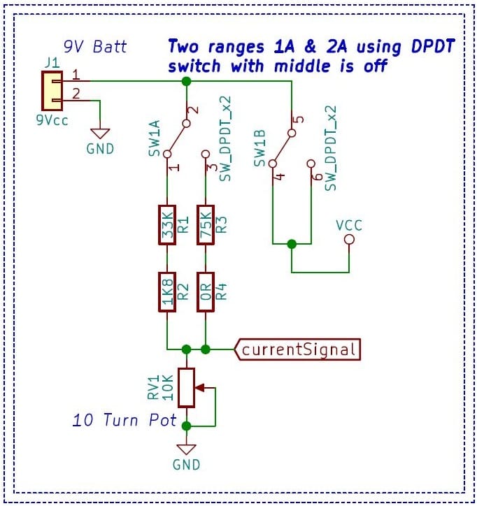
As the name suggests, the on-off switch for the device used to switch between two ranges. It is a voltage divider circuit with Dual Pole Dual Throw rocker switch with a center off. I am using a 9v battery to power this device.
Component Selection
There are no specific values of the resistor to be used. We will be using the resistors that will get us the ranges required. To keep current consumption low, we will use high values of resistances. This circuit is not ideal because the voltage range will change as the battery voltage drops over time. To avoid this, a voltage regulator or a voltage reference can set constant voltage.
Also, a multi-turn potentiometer is preferred to give finer adjustments.
Main Control Loop
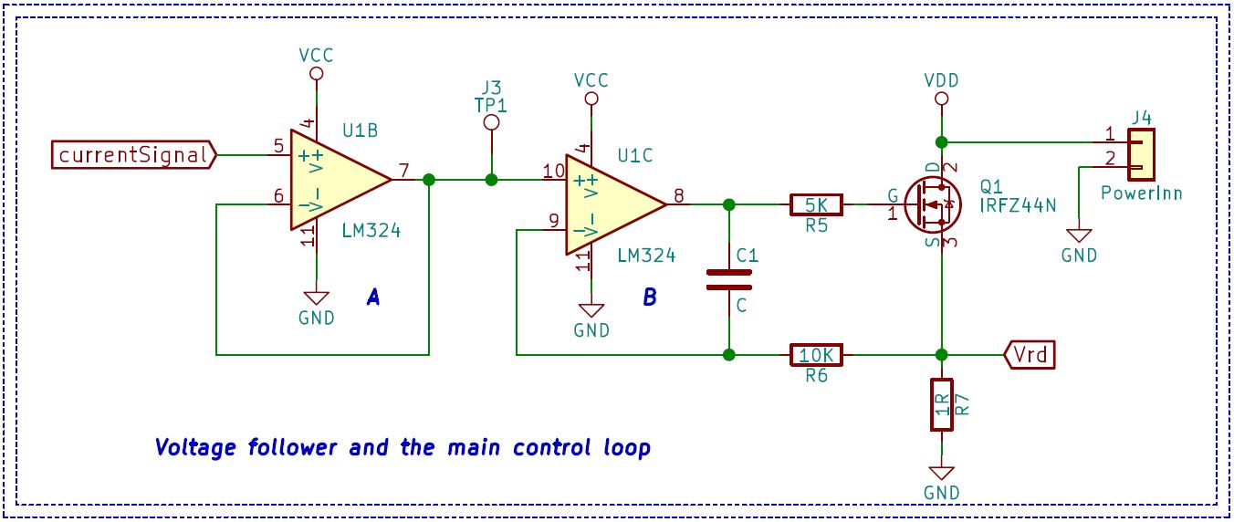
The above shown is the primary circuit that is quite simple to understand. We will first look at the individual circuit block in isolation.
Op-Amps A
The first op-amp ‘A’ from the LM324 quad op-amp is in the voltage buffer configuration. As the name suggests, the op-amp buffers the “Current Singal” coming from the potentiometer. This voltage sets the load current.
Op-Amps B
Op-amp ‘B’ compares the voltage across resistor ‘R7’ and the buffered signal. Op-amp switches the Mosfet to control the current flowing to the ‘R7’ resistor.
Circuit Operation
The potentiometer with the voltage dividing resistors set the voltage signal controlling the current flowing through the dummy load. Op-amp buffers the input signal, so the input signals are not loaded.
Op-amp golden rules state’s the op-amp will do everything at the output to keep the voltage across its input pins the same. The op-amp ‘B’ shown in the image has the buffered voltage and the voltage drop across ‘R7’ resistors at its input pins. When the voltage across R7 drops below the set voltage, the op-amp turns on the Mosfet. The current flows through the resistor R7. As soon as the voltage across R7 increases above the set voltage, the op-amp turns off the Mosfet. And so on.
Example
As we are using a 1Ω resistor, 100mV voltage drop across the resistor gives us 100mV flowing through the 1Ω resistor.
Other components
You may have noticed there are few passives in the control loop, which I have not mentioned. These passives stabilize the control loop as the op-amp drives a capacitive load that is the transistor’s gate to source parasitic capacitance. Also, there is an inductive component of the leads used to connect dummy load to the power source.
Component Selection
LM324 – I selected this op-amp because I had it lying around in my parts bin. But ideally, you will want an op-amp with a low input offset. Which also can go rail to rail at its output. Having higher voltage at the gate of Mosfet is better.
IRFZ44N – Mosfet was also selected because I had it in my parts bin. But ideally, you would want a Mosfet with a low threshold voltage or turn-on voltage. Also, the gate-to-source capacitance should be as low as possible. Lower On Resistance of the op-amp is also a plus. And it paramount to choose a package that can handle the current you need to load.
1Ω Resistance – I am using a single 1Ω resistance of 25W, 5% tolerance, but if possible, use a more accurate resistance and do the thermal calculations according to your current requirements.
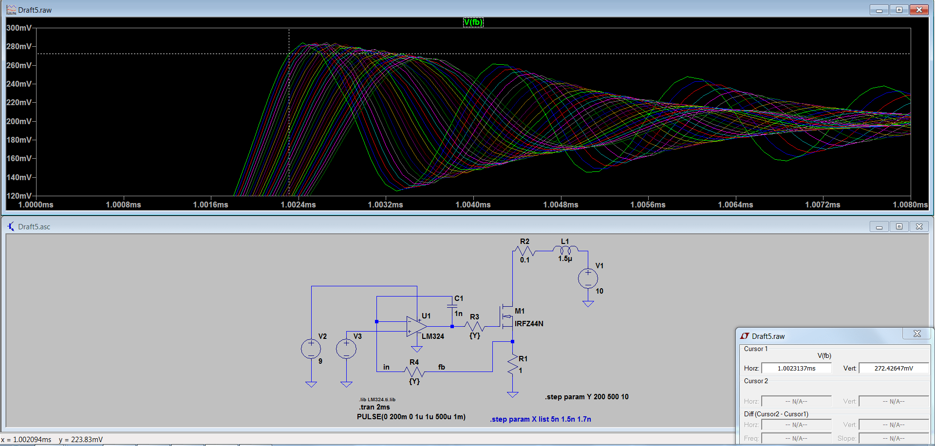
Passive Components – The value of the passive components in the control loop will change according to your transistor and op-amp. I used LTSpice to model the circuit and derives the ideal values for my selected passive components. Below is a snippet of the circuit model and the simulation output. Looks fancy. I know.
Voltage Set & Read switch
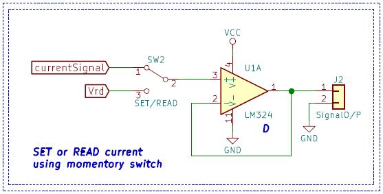
The above circuit provides a much-needed option to see the set current. As we have a 1Ω sensing resistor, 1V voltage represents 1A of current output. One can use ‘SW2’ to switch between set-current and the actual voltage drop across the resistor. Both the signals are buffered using the ‘D’ op-amp to avoid loading the circuit. The output goes to a banana plug on the side of the device. Currently, the op-amp is just a buffer amplifier. But it can be configured to have a higher gain to read smaller voltages when using a lower value sense resistor.
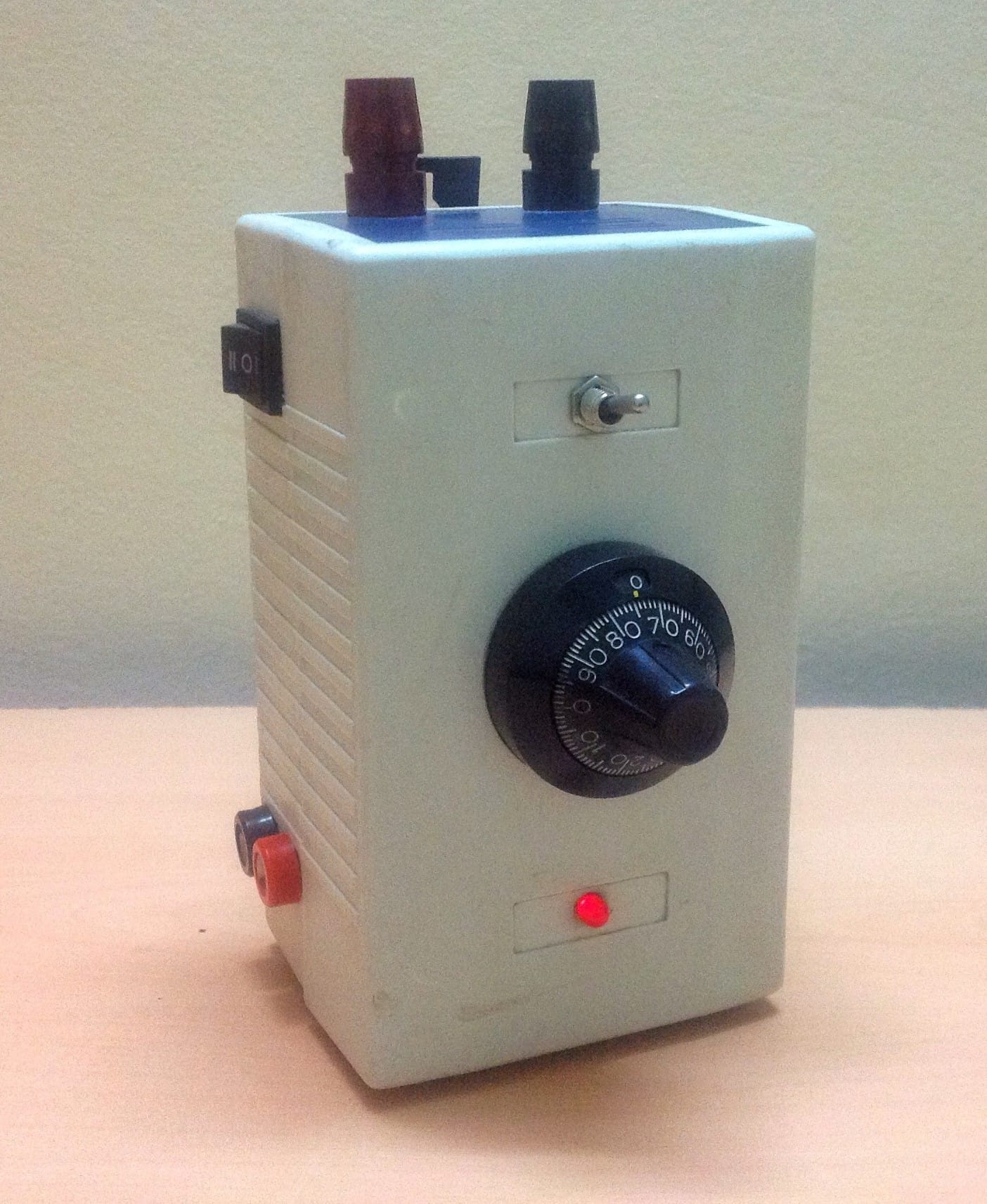
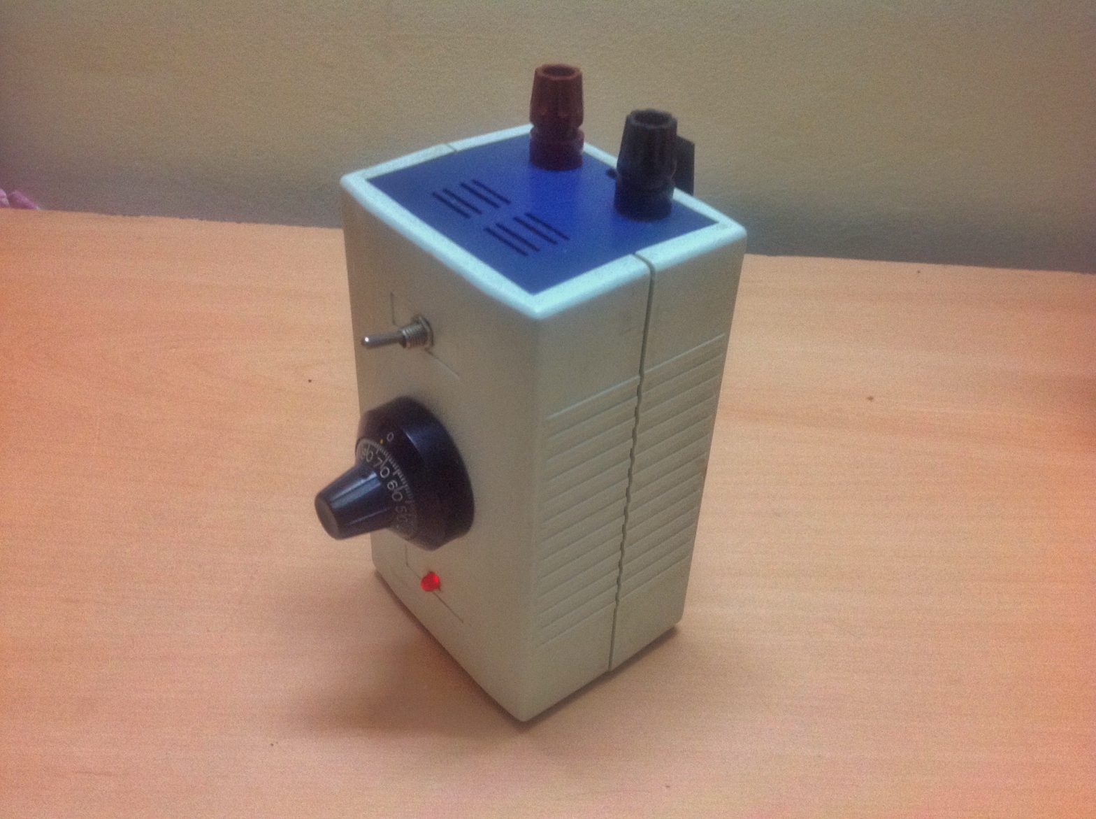
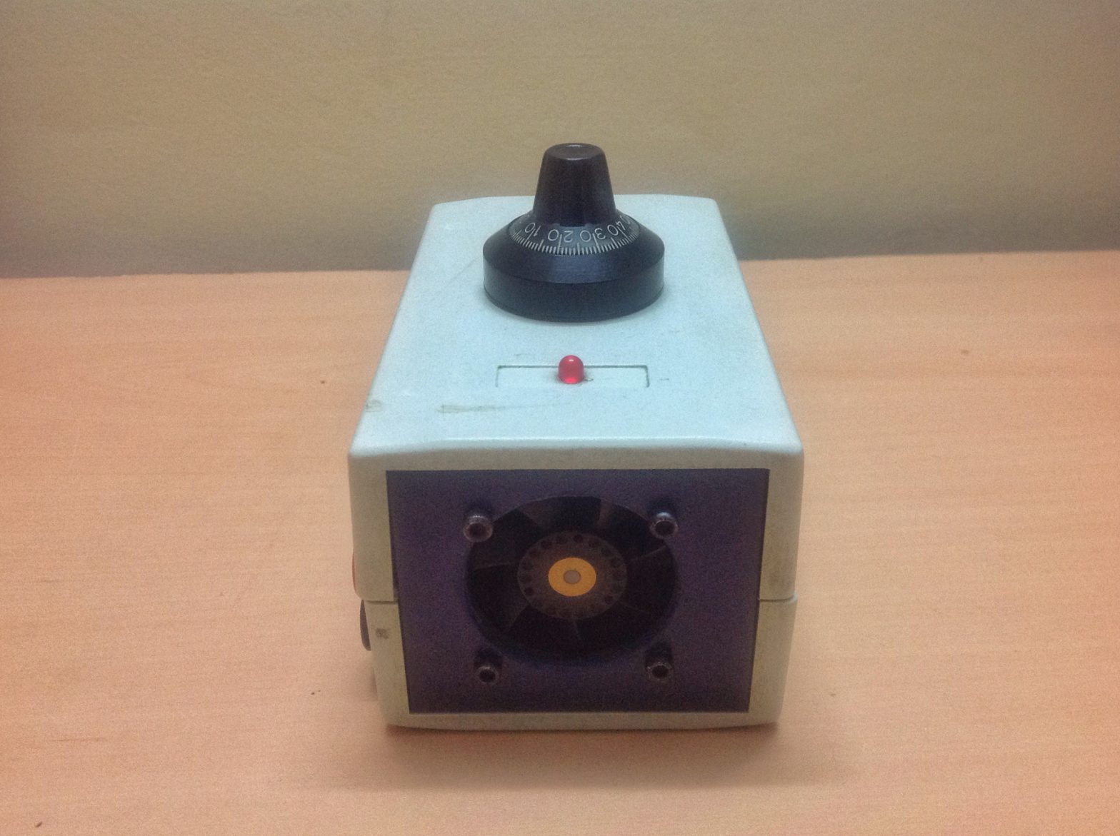
Following are a few photos of the device from different angles. And a few from the inside of the enclosure.
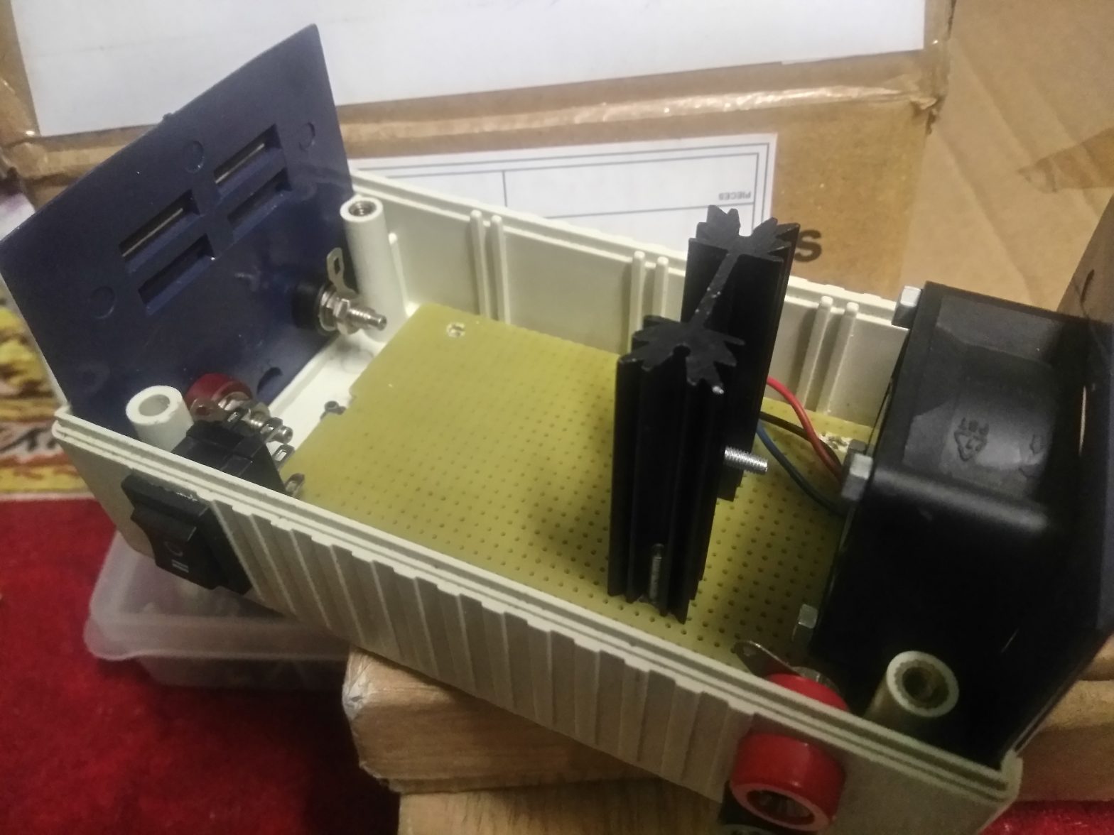
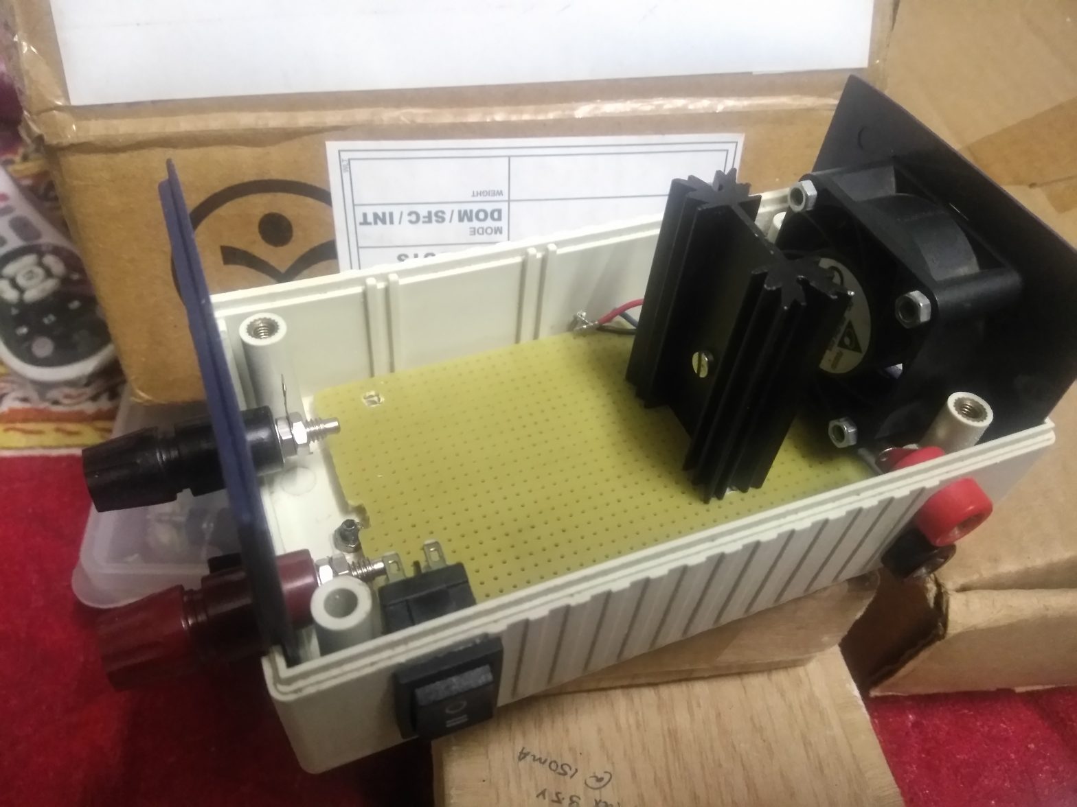
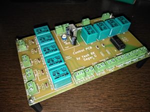
Currently, I am designing PCB for the device. The current circuit is made on a prototyping board and is messy in terms of its wiring. Also, I will be adding a DC fan to the device to get a better cooling performance which I will be updating in my next blog post.
See you then.

Pingback: Inductor Saturation Current Measurement Jig and Constant Current Dummy Load – Infinus Electronics
Hi from Italy!
Thumbs up! Thank you for the article, very well made. I’m looking for a 10A version, I’m at my first experiments with opamps, not sure I can make it by myself in a short time! IRFZ44N is one of my fav parts together with LM317, made many projects with these two.