
When it comes to embedded systems, the most important thing is the execution time required for your main loop. It determines your system’s responsiveness and power consumption. To drive that point home, today, we will see how to interface a rotary encoder to an STM32. And shorten the time spent in the control loop by using peripherals.
Tip: Use microcontroller’s peripherals where ever possible and free up your CPU for other tasks.
Just a quick explainer. In most of the microcontroller based applications, we broadly do two things, set up the microcontroller and second is to do a task repeatedly. We want to complete this repeating task as fast as possible, so in the physical world, the action seems instantaneous. For example, no one wants a keyboard which has a couple of seconds of input lag. To achieve low lag time microcontrollers are equipped with peripherals. These peripherals are nothing but hardware blocks which do just one task quickly and efficiently while freeing CPU to perform other tasks or to put the CPU to sleep and conserve power.
Let’s take a practical example and get our hands dirty!
We want to interface a rotary encoder to an STM32 microcontroller.
A standard way of doing it would be to use a couple of interrupts pins to increment or decrement a global counter variable depending upon the polarity of the pulses. The variable is ‘global’ as it needed to be accessed by both the main loop as well as the interrupt service routine.
As you can imagine, the CPU will be interrupted many times during its operation.
But there is a better way.
While mucking around with Nucleo Board, I found the timer in the STM32 used on the board has an encoder mode which will count the pulses and automatically increment or decrement the counter value according to the direction. And the CPU can access the counter register whenever needed.
Here is how to set this timer using STM32 Cube IDE.
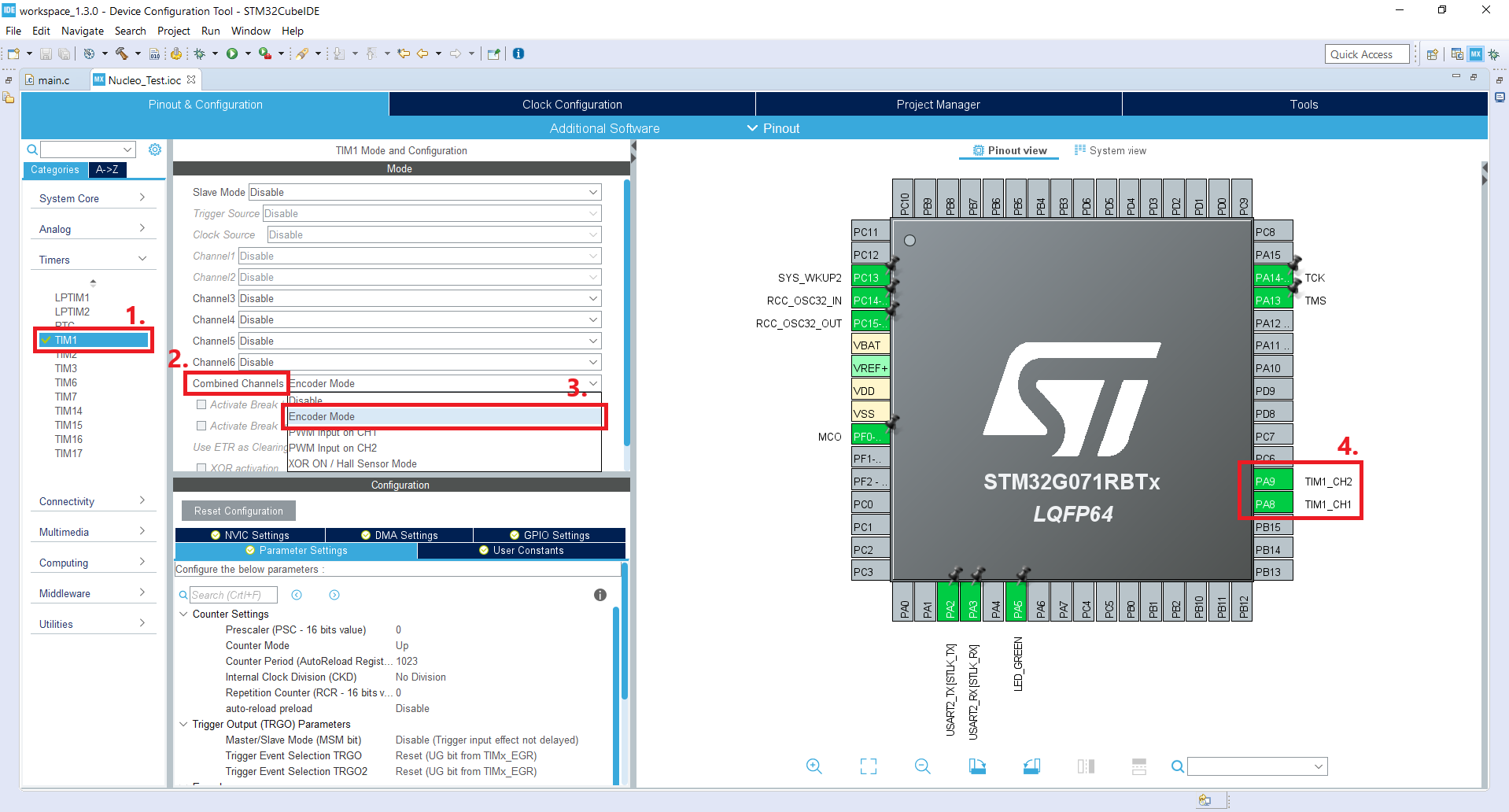
Here we are using TIM1 with its combined channels are set to ‘Encoder Mode’.
You will notice PA8 & PA9 pins turned green and automatically named as TIM1_CH1 & TIM1_CH2.
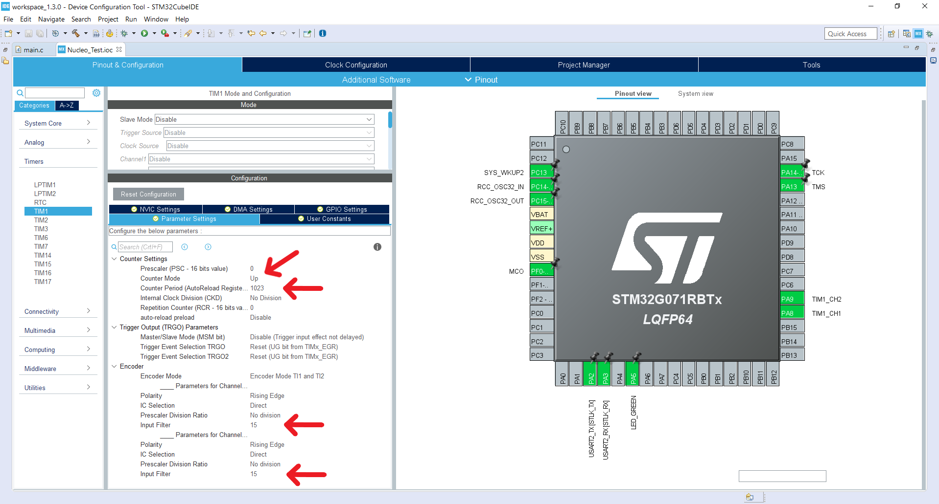
We have set up the counter mode to be counting up. Here counter is set up to count up to 1023. 1023 is just a round number (*wink* *wink*) you can choose any number less than or equal to the size of the counter register, in this case for 16 bit register it will be 65,535.
In channel’s parameters, we will set Input Filter to 15 this will filter out the debounce issue and keep the rest as default.
I have also used a UART output on pins PA2 & PA3 to output counter value to a terminal.
Let’s now take a look at the code, its quite simple.
We want a timer to count and handle the encoder. The main loop will print the counter value on the serial terminal, only when encoder value changes.
Here we add a stdio.h library as we will be using sprintf function.
/* USER CODE BEGIN Includes */
#include <stdio.h>
/* USER CODE END Includes */
We have a couple of integer variables ‘i’ just as a temporary variable and ‘pastI’ keeping its past value. Also, we will be using a character array to hold the ASCII value of the counter variable.
int i = 0, pastI = 0;
char var[20];
Here we define the infinite loop. In which, we first get the current counter value and compare it to the last value. If the value changes, we will print it to UART also toggle an LED just as visual feedback. Finally, we update the pastI value.
while (1)
{
  /* USER CODE END WHILE */
  /* USER CODE BEGIN 3 */
  i = TIM1->CNT;
  if (i != pastI){
    HAL_UART_Transmit(&huart2, (uint8_t*)var, sprintf(var, "%d\n", i), 500);
    HAL_GPIO_TogglePin(LED_GREEN_GPIO_Port, LED_GREEN_Pin);
  }
  pastI = i;
}
/* USER CODE END 3 */
Here we can see the serial output from the controller. I am using Arduino’s serial terminal as it is simple and works without hassle.
Notice that the counter value resets after reaching 1023 as intended.
In conclusion, we can see the timer peripheral offloaded CPU task of handling input pulses generated by the encoder. Similarly, we can offload other tasks like copying data from a memory location to another using DMA.