One of the most important components you will ever encounter in electronics is MOSFET (Metal Oxide Semiconductor Field-Effect Transistor), it’s easy to use, can handle high voltages and high currents, have high switching frequency compared to BJT. And they are nearly everywhere. So it’s important to understand how they work and more importantly how to use them in practical day to day circuits.
First things first, if want to get a basic guide to MOSFET, there are better sources online –
There is Afrotechmods Youtube Video – Link
OR
A written article on Instructables – Link
They will give you a good foundation to understand the topics we are going to discuss in subsequent posts. This and upcoming posts are more of a next step in using MOSFETs.
Let us start by understanding what type of MOSFET you will encounter and the appropriate way to use them.
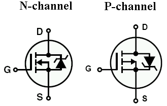
There are two types of MOSFETs N-channel & P-channel MOSFETs
Both MOSFETs have 3 pins gate, drain, and source. Gate pin is where you provide a signal to turn MOSFET on. This signal is called Gate to Source Voltage (Vgs) in the datasheet.
We are going to mainly talk about IRF540 here is the datasheet and IRF9540 (datasheet).
In the case of N- channel MOSFET when the Vgs is high the transistor is on and when Vgs is low the transistor is off.
In the case of P- channel MOSFET it’s opposite when the Vgs is high the transistor is off and when Vgs is low the transistor is on.
So far so good.
Bear with me, the good stuff is coming.
To get a real sense of MOSFETs to let us first understand why we just don’t use a BJT everywhere.
BJTs are great we can drive BJT’s in cutoff and saturation region (wiki link) and make it work like a MOSFET, newer BJT also now can handle high voltages and current.
But still we prefer MOSFETs over BJTs there are numerous differences between them but mostly you will be limited with is their ‘switching frequency’ and ‘driving current’.
In the case of BJT, there will be a minority carrier stored in the base when it is in saturation region which will take time to flush out while switching BJT off.
And since BJT is a current control device (i.e. controlled by the current flowing through the base),
Ic (current flowing through collector) = ß (current gain) x Ib (current flowing through base).
Thus to drive high current through BJT we will need high current on the base, which your microcontroller might not be able to provide. Thus driving multiple of them just makes things worst.
Here MOSFETs are handy they are voltage controlled devices thus the voltage at the gate will control the MOSFET while consuming less current which not only helps driving multiple MOSFETs easy but also helps MOSFET to work at high frequencies as it has to flush less charge while switching MOSFET off.
So how do you decide how much voltage to put on the gate? It’s easy to just go to the respective datasheet and use the value given by Vgs on the first page. Do note this value is with respect to source voltage not with respect to ground(0V). We will dive into this more in the upcoming post.
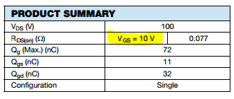
IRF540 Datasheet showing Gate to Source Voltage 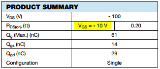
IRF9540 Datasheet showing Gate to Source Voltage
That’s it for this post hope you learned something, if not don’t worry in next post we will unravel the mysteries of the high side and low side switching, choosing the right MOSFET for the job and try to understand why we use N- channel MOSFET more than P- channel.

